Hola, y bienvenidos. Es tiempo de crear nuestra primer arma en OFP. Si, así es. Un tutorial paso a paso que cubrirá todo el proceso, desde el modelado de dicha arma, hasta el meterla en el juego.
bien, que vamos a necesitar. Veamos
OFP (obviamente). el programa O2 y Bulldozer Un entendimiento básico de la interfaz del O2 Tener un conocimiento completo de la lección 1 (como crear LODs, Selección, etc.) También, si completaste la lección 2, esta debería ser una lección sencilla. PBOTool y TexView
Ok, esas son las cosas mas importantes. Echemos un vistazo al modelo que vamos a crear
El arma
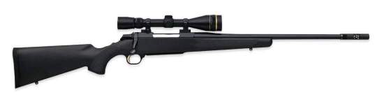
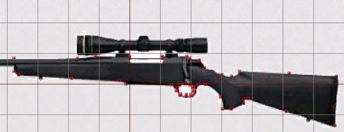
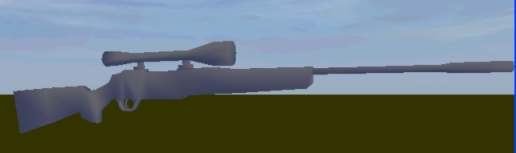
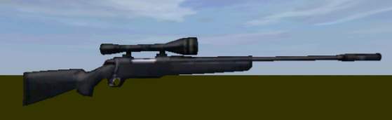
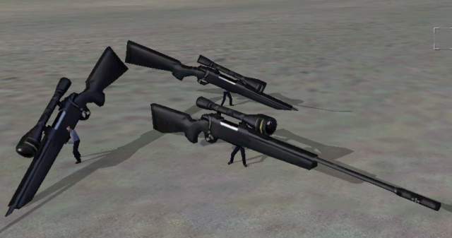
El arma que vamos a crear se apoda 'Stalker' y es un rifle de francotirador de Browning. Échale un vistazo:
Copada no? Bien, puede que no le guste a todos, pero es el arma que vamos a crear. Se preguntaran por que? Primero tenemos una gran vista del arma en esa pagina, que es mayormente negra (lo que hace que las texturas sean mas fáciles) y segundo, y mas importante, luce espectacular
Entonces, lo que tienes que hacer para comenzar es:
+ Ve a donde tienes instalado el Bulldozer y crea una carpeta con el nombre 'stalker' + Descarga el archivo de texturas de aqui y extráela en la carpeta previamente creada.
Cuando estés listo para comenzar, ve al siguiente punto.
Colocando los vértices
Primero debemos crear el modelo actual del arma. Haz esto:
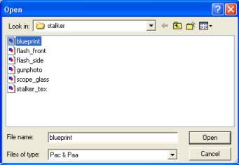
+ Inicia el O2 y Bulldozer, y guarda el nuevo archivo como stalker.p3d en la carpeta que habían creado + Activa la vista frontal (front view), presiona A y luego con el click derecho selecciona 'load Texture'. Encuentra la carpeta 'stalker' y carga el archivo 'blueprint.paa'
Load the texture we are going to use as reference.
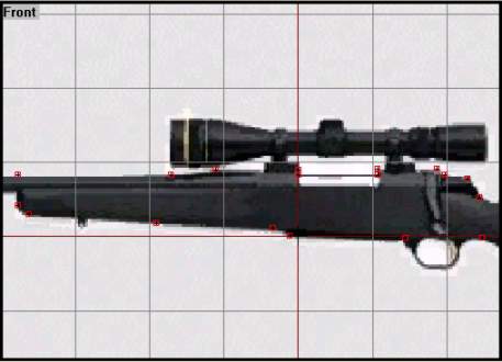
+ La imagen ocupara el 80% de la cuadricula, entonces debes hacer click con el botón derecho y seleccionar 'correct aspect' para asegurarte que la misma este en la escala correcta. También selecciona 'Horizontal Mirror' desde el mismo menú, así el modelo se refleja desde la izquierda + Presiona F4 para salir del modo de textura (texture mode). La vista frontal debería lucir así
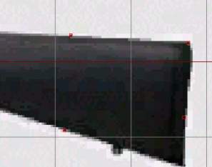
Ahora debemos modelar el lado del arma. Lo vamos a hacer remarcando el perfil del arma con vértices. Eso significa que vamos a insertar varios puntos al rededor del modelo. Mas tarde crearemos caras a partir de estos vértices. Comencemos con la culata.
Realizamos un Zoom en la parte del arma y comenzamos a colocar vértices usando el cursor y la tecla 'Insert'. Comienza de cualquier lado y trabaja al rededor de la imagen. Insertar los vértices en el lugar preciso no es algo que puedes aprender así como así, solo con experiencia de modelado. Pruebas y errores, solo eso. Así es como quedaría:
Nótese que hay unos pocos vértices en los puntos 'lisos' y mas vértices en los lugares mas 'redondeados'. Recuerden que estamos lidiando con polígonos, que mas tarde uniremos con líneas. Entonces, necesitamos tener mas vértices donde el modelo supuestamente tiene un borde mas redondo.
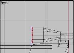
Ahora echemos un vistazo a la zona media (deja afuera el área del gatillo y de la mira telescópica por ahora). Lo que sugiero:
No luce tan mal verdad? la zona media esta ahi, al menos, nota que no fui mas allá, es porque el cañón del arma será creado con un pequeño cilindro, lo mismo que la mira, pero mas adelante.
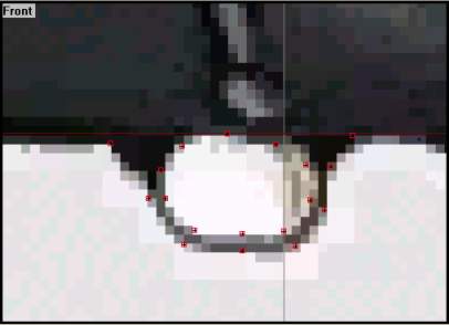
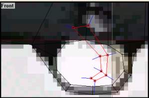
Ahora para la zona del gatillo, es una vista que debe ser redonda, lo que conlleva muchos vértices para lucir bien. Recuerda que ese área entre vértices será conectado con caras, entonces necesitamos crear el anillo interno y el externo, algo así:
Ok, aun no queda perfecto. Es algo difícil de imaginar como los vértices lucirán una vez que se conviertan en caras, pero no te preocupes. Es fácil moverlos luego. Y todavía no creamos el gatillo, pero lo haremos mas adelante.
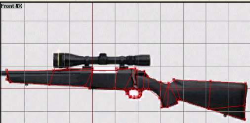
Como debe lucir nuestra Stalker hasta ahora.
Cuando estés contento con tus vértices (si no es así, muévelos, agrega o quita algunos para que queden mejor), ve al siguiente paso. Y no te preocupes si alguno se sale de la imagen, es solo para referencia, para la textura vamos a usar otra.
Creando Caras
Ahora es tiempo de que los vértices hagan su trabajo. Vamos a empezar con la culata. Crear caras es fácil, selecciona 3 o cuatro vértices y presiona F6 para crear una cara. Si leíste algunos tutoriales básicos de O2, sabrás que cada cara es una 'face normal' o una 'direction'. Eso significa que una cara es normal solo viéndola desde un lado. Voy a asumir que ya conocen un poco sobre esto (si no, busquen un tutorial de la interfaz de O2 o cualquier programa 3d que utilice modelado de polígonos)
También habrán escuchado que el O2 soporta caras con cuatro vértices y no solo con 3 como los grandes programas (3dsmax, etc.). Eso permite que usemos menos caras en modo normal y aun que usemos caras con 3 vértices cuando lo necesitemos. Seleccionaremos 4 o 3 vértices y crearemos caras sobre ellos usando la tecla F6. Sean cuidadosos de no superponer las caras, porque eso hará que se vea mal en el juego.
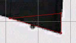
Te mostrare como hacer tu primera cara (Face):
+ Haz zoom en la sección del arma que quieras. Vamos a comenzar con una cara de cuatro vértices. + Selecciona los cuatro vértices que te indico en la imagen:
+ Presiona F6 y la cara debería de aparecer.
Ahora debemos asegurarnos que esa cara esta 'apuntando' al lugar correcto. Cuando hice esto, la dirección de la cara iba desde mi y no hacia mi como lo quería. Entonces debemos cambiar la dirección de la cara para ponerla del lado correcto. Recuerda el truco que mencione en la lección 1, como hacer para ver si la cara te mira? selecciona la cara, y ve al menú 'View - Fill solid faces'. Ahora si la cara se torna roja, sabrás que la cara va hacia ti, pero si parece desaparecer (ya que se tornara negra y será difícil de divisar entre las texturas del mismo color) significa que la cara esta del lado incorrecto. Para cambiar la dirección de la cara, presiona la tecla W. Recuerda que debes hacer todas las caras del mismo lado.
Ahora tenemos nuestra primer cara. Noten que luego de crear esa cara de cuatro vértices, mas abajo solo nos quedan tres vértices. Selecciónalas usando F4 (en el modo vertex select) y presiona nuevamente F6. Ahora O2 es muy inteligente y debería hacer la cara de la misma dirección que la anterior, pero para estar seguros, usen el truco de 'Fill Solid faces'.
Ahora, trabaja al rededor del arma creando caras entre los vértices. Crea caras de 4 vértices cuando puedas, y cuando no, créalas de 3 vértices. Asegúrate de que todas las caras vean hacia el mismo lado. Puedes borra una cara, sin borra los vértices, solo selecciona la cara (con F4 sobre todos los vértices) y bórralas presionando la tecla D
Así debería lucir cuando termines:
Otra manera de estar seguros si todas las caras están hacia un solo lado es usando la vista 3d con 'Face Culling' cambiándola desde (View - Face Culling o la tecla F).
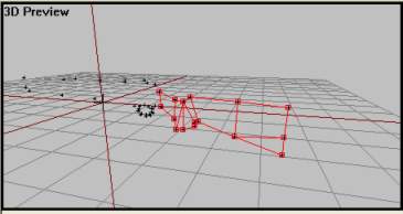
Vista 3D con las caras seleccionadas en 'face culling'. todas las caras que muestra, están del lado correcto.
Déjenme mostrarle como esta aplicación es buena para buscar caras en lados incorrectos. Voy a seleccionar una de las caras y la voy a cambiar. Vean lo que sucede en la vista 3D:
Vista 3d con las caras seleccionadas en 'face culling'. Ahora aparece un hueco en la estructura, lo que significa que una cara esta del lado incorrecto.
Vista 3d con las caras seleccionadas en 'Face Culling'. Si movemos la cámara y echamos un vistazo en la parte trasera, encontraremos nuestra cara ausente. Como pueden ver, esta es una manera mucho mejor y mas rápida de encontrar caras incorrectas que la mencionada anteriormente (truco de 'Fill solid face').
Ahora, si ya haz entendido de que se trata, crea el resto de las caras del modelo. Solo se precavido, hazlo de forma lenta, para asegurarte que lo haces de la manera correcta y que no hay caras en lados erróneos o superpuestas. Aquí hay algunas capturas de como debería quedar:
Deberíamos seguir adelante.
Aplicando la Profundidad
Entonces, nuestro modelo básico va tomando forma. Hasta incluso luce como un arma. Pero eso solo en la vista frontal ( y finalmente, si te haz estado preguntando por que hemos estado usando la vista frontal para nuestra vista lateral, es porque es la manera de hacerlo con las armas. No se por que. Pero si no lo hacemos así, el arma se posicionara en el lado incorrecto cuando alguien trate de usarlo en el juego). Bien, ahora que tenemos el plano completo vamos a hacer algo con eso:
+ Selecciona la estructura usando Ctrl+A (o F2 en cada vértice). + Activa la vista izquierda (left view) sin perder la selección (alt + botón derecho del mouse)
+ Ahora presiona Ctrl+C para copiar la estructura. Luego presiona Ctrl+V para pegarla en una nueva copia. Esta será de la misma escala que la original. + seleccionen el eje X y muevan la copia un poco a la derecha usando el botón derecho del mouse.
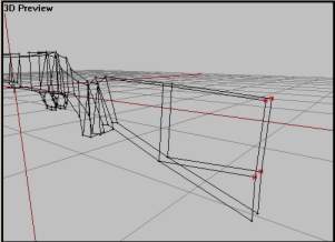
+ Noten que las caras de la copia están de la misma manera que la original, hacia la izquierda. Pero nosotros queremos que vayan para el otro punto, entonces con la copia aun seleccionada presionamos la tecla W para cambiar el sentido. + Ahora debería de lucir así:
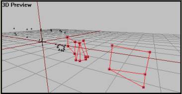
La vista de frente, y la 3d con ambas estructuras seleccionadas. Noten que no se encuentra en 'Face Culling' para mostrar todo como una sola imagen.
Ahora debemos unir los dos lados. Eso significa seleccionar 4 y 4 vértices y crear una cara. La manera mas fácil de hacer esto es usando la vista 3d. La parte difícil de esto es colocara la cámara en el lugar correcto y seleccionar los vértices correctos. Pero los voy a ayudar con el primero:
+ Posicionen la cámara como en la imagen debajo y seleccionen los vértices iluminados.
Vista 3d sin 'face culling'.
+ Presiona F6 para crear una cara. Luego de esto asegúrate de que hay líneas azules apuntando hacia afuera de la estructura como en la imagen de abajo. Utiliza la tecla W para colocar la cara si no lo están de la forma correcta.
Vista 3d sin 'face culling'.
Haz lo mismo para todo el modelo! Si, es un trabajo difícil y aburrido, pero es una buena practica de modelado. Asegúrate de seleccionar los vértices correctos, ya que es muy fácil seleccionar el incorrecto si tienes la cámara en una mala posición. Usa la vista 3d, y la otra vista como guía. Por ultimo utiliza el Bulldozer y 'Face Culling' en la vista 3d para buscar caras hacia adentro o perdidas.
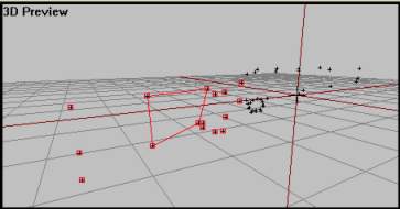
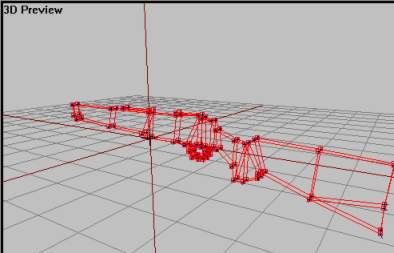
Al final, debería de lucir así:
Vista 3d sin 'face culling'.
Vista del Bulldozer.
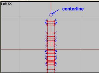
Una cosa mas, después de que hayas terminado, selecciona todo presionando Ctrl+A. Luego en la vista izquierda, selecciona el eje X y muévelo hacia la izquierda. Trata de colocarlo al medio de la línea roja, que se encuentra en el centro del Grid, justo como en la imagen de abajo.
Eso fue mucho trabajo, no crees?. Bueno, es un placer decirte que la parte mas difícil a terminado. Si lo lograste hasta ahora, estarás bien en los próximos pasos también.
Cañón y Mira telescópica
Nuestra armas ahora es realmente 3d, pero nos falta algo, en al sección del frente. Lo vamos a hacer con un cilindro estándar:
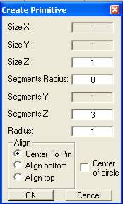
+ Activa la vista izquierda (left view) y presiona F8 para crear un cilindro. En la pestaña 'segmenta radias' coloca el numero 8 y en 'segmenta Z' el numero 3. Luego presiona 'OK'.
+ En la vista 3d veras un cilindro. Esta colocado en la dirección correcta pero aun necesitamos escalarlo.
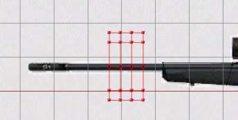
+ Ve a la vista frontal, y usa el botón derecho del mouse para mover el cilindro a esta posición:
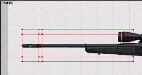
+ Bloquea el eje X presionando la tecla X. Selección cada columna de vértices con la tecla F4, y muévelo de tal manera que la posición quede mas o menos como en la imagen.
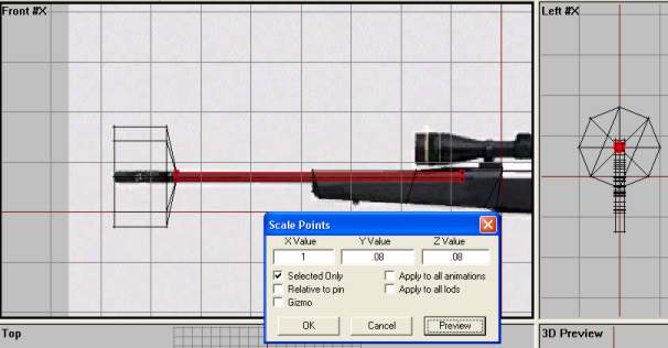
+ Selecciona las dos columnas que quedaron mas a la derecha, ten cuidado de no seleccionar los vértices de la estructura principal del arma. Selecciona 'Points->Transform3d->Scale' desde el menú. Deja el valor del eje X en 1 y trata de encontrar un valor decente para el eje Z y el eje Y (sea cual sea el valor, tanto el de Z como el de Y tienen que ser el mismo, sino el cilindro lucirá algo 'exprimido') No te puedo dar un valor exacto, porque tu visión de modelo no va a ser igual a la mía, pero para mi, al rededor de 0.1, en el eje Z y el eje Y funcionarán bien.
+ Haz lo mismo con las columnas restante, pero mantén el valor de Z y de Y un poco mas alto, porque el cañón es mas grande en la punta. Para mi, un valor de 0.12 para esos ejes funciona bien.
Al final, debería de lucir así:
Ahora tenemos que crear la mira, obviamente vamos a usar el mismo proceso. Creamos un cilindro con varias divisiones y escalamos cada una de ellas. También vamos a necesitar dos cubos para los soportes de la mira.
+ Activen la vista izquierda, presionen F8 y coloquen los siguientes valores:
+ Ve a la vista frontal y mueve el cilindro así:
+ Entonces, como hicimos con el cañón, bloqueamos el eje X y seleccionamos cada columna, y la movemos hasta que luzcan así.
+ Sigue siendo igual que antes, usa la escala 3d para conseguir una correcta vista, que se parezca a una mira telescópica. Como ya dije, tus valores no serán los mismo que los míos, así que experimenta un poco con los ejes Y y Z. Pero no toques el eje X.
Al finalizar, debería de lucir así:
después vamos a necesitar los dos bloques que mantienen la mira en su lugar. Esto va a ser fácil para ti, solo tienes que posicionar varios vértices en sus respectivos lugares, crear las caras de forma correcta y luego darle la profundidad como lo hicimos con la parte principal del arma.
Aquí esta uno que yo hice:
Los dos soportes para la mira (Nota: Muévanlos fuera de la estructura del arma solo para poder verlos mejor)
Algo mas? Si, el gatillo. No aparece en la imagen, entonces esta vez solo vamos a usar nuestra imaginación de modeladores. Esto es solo un tutorial, y el modelo que estamos creando es un hermoso modelo 'low poly' o de bajos polígonos. Aquí esta como lo hice yo:
La estructura del gatillo (Nota: Muévanlos fuera de la estructura del arma solo para poder verlos mejor)
Lo haz echo. El modelo esta finalizado!
Ahora vamos a aplicarle algunas texturas, quieres?
Texturas
Ahora debemos ponerle algunas buenas texturas sobre el color gris básico. Todas las texturas están en el archivo .zip que descargaste al principio, y que ahora se muestran en la carpeta 'stalker'. Veamos:
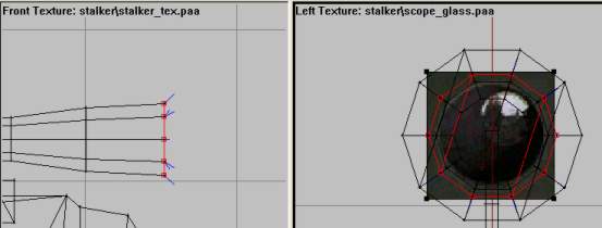
+ En la vista frontal, utilizamos la combinación de tecla Ctrl+A para seleccionar todo, una vez echo esto todo se tornara rojo. Presiona A, después el botón derecho del mouse y elige 'load texture'. Carga el archivo denominado "stalker_tex.paa". después, con el click derecho del mouse elijan 'Horizontal Flip' para colocarla del lado correcto. + Ahora viene la parte difícil, escalar la textura. De modo que se ajuste a nuestro modelo de una forma bastante precisa. Usa las combinaciones de teclas Ctrl+Shift+Arriba/Abajo/Izquierda/Derecha para lograr escalar la textura. Recuerda seleccionar 'Correct Aspect' de cuando en cuando para evitar que la textura se deforme. Se que es difícil, y no se volverá mas fácil si cortamos las texturas en piezas, pero prueba de todas maneras. Y recuerda que esto es solo un tutorial, de manera que no es necesario que quede de la misma manera que las imágenes. A mi quedo algo así:
+ Cuando estés feliz, con todo seleccionado presiona la tecla B y las texturas se aplicaran al arma. Fijate ahora en el Bulldozer, nada mal no?:
Entonces, no va a ser el arma mas bonita, pero no luce mal para un tutorial de modelado. Al menos no tan mal, de todas formas. Yo pienso que luce bastante bonito. Una cosa mas, vamos a necesitar una vista frontal mucho mejor para la mira, alguna textura cristalina. Hay una en tu carpeta 'Stalker' así que vamos a aplicarla:
+ Desde la vista frontal, con el click derecho del mouse seleccionamos "unload texture" para remover la textura. Nosotros ya terminamos con esa. Ahora haz zoom sobre la parte frontal de la mira, presiona F4 y selecciona el la columna del frente de la misma, así:
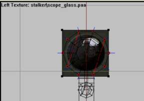
+ Activa la vista izquierda sin perder la selección (Alt + botón derecho del mouse), presiona la tecla A + el click derecho y carga la textura denominada "scope_glass.paa" + Coloca el plano de la textura sobre la cara de la mira, usa 'Correct Aspect' para asegurarte las dimensiones correctas de la imagen.
Cuando estés feliz con la ubicación de tu textura, presiona la tecla B para aplicarla. Compruébala con el Bulldozer y si te perdiste algo, intenta de vuelta. Este es mi resultado:
Ahora haz lo mismo con la otra cara de la mira. Solo sigue los mismos pasos que acabamos de realizar. Select the rear scope vertrice colum using F4 in the front view, go to left view and scale the glass texture so it fits the smaller scope end nicely. Then applying it with B and check out in Bulldozer.
Bien, este es mi resultado.
Y así se texturiza, mi amigo. Ahora el difícil modelado a concluido, solo unas simples cosas de LOD y crear una configuración básica para el arma y listo. Vayamos!
Memory LOD
Como en todos los addons de OFP, necesitamos arregla unas cosas en los LODs. Pero para un arma solo necesitamos una, la MemoryLOD (o memoria LOD) y esta solo contiene 4 vértices! Simple en verdad, comencemos:
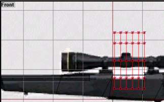
+ Crea un nuevo LOD y cámbialo a "Memory LOD" con el click derecho seleccionando "propeties". + Ve a la vista frontal y haz zoom en el cañón, como en la imagen.
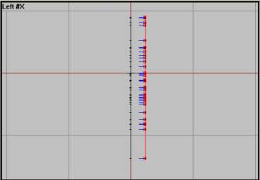
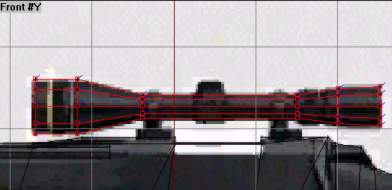
+ Coloca un vértice en el centro de cada punta del cañón. Tienen que estar a la misma altura ( o el arma no realizara el disparo), entonces, solo haz uno, puedes bloquear el eje X y duplicar el otro usando el click derecho y la tecla Shift juntos y arrastrarlo. Los resultados serian algo así:
+ Entonces, recuerdas los LODs de la lección 2?, que seleccionábamos los vértices de a uno y los nombrábamos usando palabras Checas. Bien, haz lo mismo usando las palabras en las imágenes arriba ("Konec hlavne" ) significa final del cañón y ("usti hlavne" ) comienzo del cañón. Si no sabes como guardar las selecciones, ve la lección 2.
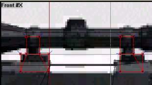
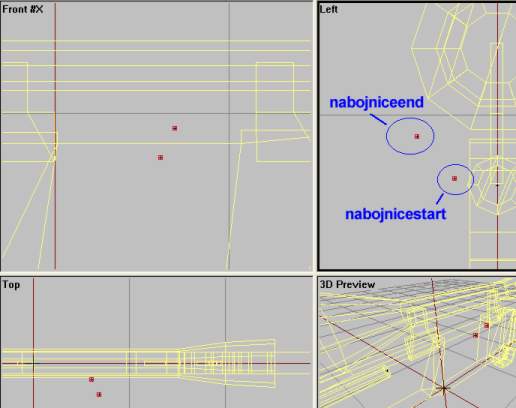
Ahora el arma puede disparar bien. Pero todavía necesitamos indicar donde el arma debería lanzar los casquillos. Como con el cañón, necesitamos empezar y parar en la posición desde donde el casquillo va a ser 'escupido' por el arma. El lugar no es tan importante, así que te voy a dar cuatro vistas de como debes posicionarla.
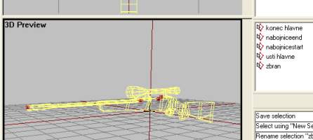
Guarda cada una de las selecciones nombradas en la imagen. "Nabojnice" significa recamara del cartucho en español.
Finalmente, necesitamos la quinta y ultima selección denominada "zbran" que simplemente significa arma. La misma consiste en seleccionar todo los vértices con Cltr y la tecla A en 'Memory LOD' y nombrarla "zbran".
Aquí una imagen de como debe quedar todo seleccionado:
Esos son todos los LODs que necesitamos para el addon de la Stalker, no bromeo. Sigamos.
El fogonazo
Bien, todavía no terminamos con las cosas del modelo. Quizas les menti un poco antes. Pero esto es muy simple.
Si todavía no lo sabian, el fogonazo que aparece cuando disparas un arma en OFP no es tiene muchos efectos especiales de luz ni otra cosa. Es solo un modelo simple con transparencia y texturas de humo sobre el que acurre un segundo después de que ocurre el disparo del arma. Decepcionado? no deberías, porque es fácil de hacer y luce muy bien de todas formas.
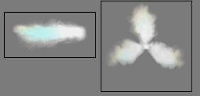
Echa un vistazo en tu carpeta 'stalker' y observa las dos texturas flash_side.paa y flash_front.paa.
Terminemos con esto:
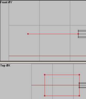
+ Ve al LOD "0.000". + Activa la vista superior (top view) y luego busca en el menú "create-plane". Presiona OK. Justo después de esto presiona F6. Las líneas azules (que indican la dirección de la cara) deberían de haber desaparecido, entonces ahora el plano es de doble cara. + Ahora mueve el plano sobre el eje X en la vista superior (recuerda bloquear el eje con la tecla X) haciéndolo mas un rectángulo. Luego en la vista frontal, bloquea el eje Y con la tecla Y, muévelo hacia arriba. debería de quedar algo así:
+ Ahora apliquemos la textura flash_side.paa sobre el plano. Ya que el plano es de doble lado, las texturas se verán de ambos lados. Activa la vista superior, haz un zoom sobre el plano y presiona la tecla A, luego selecciona 'Load texture', carga la textura flash_side.paa y arrástrala al rededor del plano. Asegúrate de que ambos lados del plano están seleccionados, no solo uno. Hazlo estando seguro que ambos lados están en gris en el Bulldozer. Si uno es rojo como el resto del arma, usa la tecla F2 y selecciona un vértice del plano. Luego aplica la textura usando la tecla B. + Compruébalo en Bulldozer. debería de lucir así:
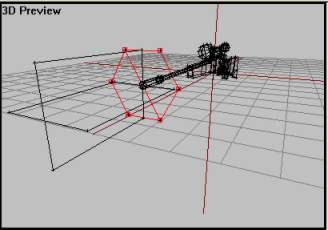
+ Ahora ya tenemos un fogonazo horizontal, también vamos a necesitar uno vertical, pero esta vez simplemente vamos a copiar el plano que hicimos y lo vamos a rotar. + Selecciona el plano con el fogonazo, usa Ctrl+C para copiar y Ctrl+V para pegar. Luego sobre el menú encuentra Transform3d->Rotate y rotalo unos 90° sobre el eje X (sobre la vista frontal) el resultado:
Vamos a necesitar otro fogonazo del cañón, un circulo para la textura flash_front.paa que será visible cuando miras el arma de frente.
+ Activa la vista lateral y busca create->circle en el menú. Haz que el radio sea de 10 a 6 y presiona OK. Mueve y escala el circulo de manera que luzca así en al vista 3D:
3d view with face culling OFF
+ Pero necesitamos caras de dos lados, entonces con el circulo seleccionado, presiona D para borrar todas las caras de manera que solo queden los vértices, así:
Vista 3d sin 'face culling'.
+ Ahora vamos a crear caras de dos lados usando la tecla F6 en cada cara. Selecciona los cuatro vértices superiores y presiona F6.
+ Entonces selecciona los 4 vértices restantes y presiona F6 para crear la cara inferior.
+ Si hiciste todo bien, deberías ver una forma redondeada al final del cañón con los dos lados visibles en el Bulldozer.
Hora lo tenemos que texturizar. Es fácil no? ya los haz echo antes. Solo selecciona el circulo usando F2, luego presiona la tecla A, carga la textura flash_front.paa, arrástrala al rededor del circulo en la vista lateral y aplícala usando la tecla B. Una rutina no crees? Pronto se hará algo natural, espero, de todas maneras, este es el resultado:
Ok, ya casi terminamos con el modelo... espera un momento. Necesitamos nombrar dos simples selecciones en nuestro primer LOD, "0.000". OFP necesita saber que parte es el modelo del arma y cual es el fogonazo del cañón. Entonces selecciona todas las partes del fogonazo (tres estructuras: dos planos y un circulo), y nómbralo "zasleh" ("flash") en la ventana de nombre de la selección. Luego necesitas seleccionar el resto de las partes (el cañón, el cuerpo del rifle, la mira, el gatillo hmm..algo mas?..no) y nombrarlo "zbran" (arma).
Y si hiciste todo correctamente, haz finalizado con el modelo! Gran trabajo. Echa un vistazo a los pasos previos y asegúrate de que todo este correctamente. Y revisa si las texturas estén bien (lo aprendimos en la lección 1). OK, esta echo? entonces pasemos a la configuración del archivo.
Configurando los archivos del arma
Solo un obstáculo nos aleja de poder probar nuestro arma en el juego. Ahora, eso debe ser algo buen, no?. Lo malo es que la configuración de los archivos es muy confuso para los principiantes. Entonces, si no lo hicieron antes, solo voy a explicar algunos puntos claves, y dejar las clases sobre esto para otro tutorial. Pueden pasar al siguiente paso si quieren, pero les pido que lean esto y traten de copiar la configuración.
Fragmento de la parte mas importante del archivo de configuración. Hay mas cosas en el mismo, pero esta es la parte que nos interesa en estos momentos.
Si tienes experiencia en programación, veras que esto es algo 'robado', la mayoría del rifle de francotirador M21, con unos pocos cambios en sus atributos. La munición es la regular, y tanto el arma como la munición tiene el mismo nombre ( entonces si vas a agregar el arma y la munición en el editor deberás escribir esto AddWeapon "Stalker"; AddMagazine "Stalker";. El nombre que aparecerá será "Stalker Sniper Rifle" y les dejo preparado una imagen pequeña del arma para el juego, la cual aparecerá en la pantalla del mapa llamada "photo.pac".
También les dejo equipo civil que e creado, se llama "Stalker Hunter" y trae el rifle con cuatro cargadores, que a su vez traen 20 balas cada uno, como el M21.
Ok, deja la configuración del archivo, vayamos a testear el modelo en el juego.
Finalizando
OK, hagamos esto. Es tiempo de probarlo en el juego. Inicia el programa PBOTool, selecciona la carpeta Stalker y guárdala como stalker.pbo en la carpeta addons de OPF. Luego inicia el juego, ve al editor y encuentra la unidad "Stalker Hunter" en Civilian->Man list. Y luego vuelve al lección después de finalizar la prueba.
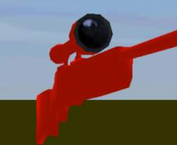
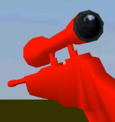
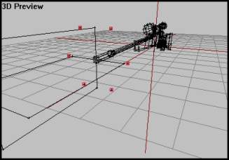
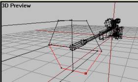
Haz vuelto? Que? Algo anda mal dices? El arma es mas grande que un avión? Algo así por ejemplo:
Ahora esto debería de ser divertido en multijugador. Pero es mas parecido al "Big Bertha" (cañón alemán de la primera guerra mundial) que al "Stalker"...
OK, no esta a una escala correcta todavía, pero al menos esta en la dirección correcta! y funciona no es así? Con sonido, recamara, fogonazo y una mira apropiada? no esta mal eh?
Necesitas usar la escala 3d en el O2 para crear el tamaño correcto (recuerda cuando realizas la escala clickea "Apply to all LODs" para que los vértices en la memoria del LOD siga el resto del modelo). Normalmente esto es prueba y error. Escálalo un poco, guárdalo y pruébalo. Si sigue siendo muy grande, hazlo una vez mas. No estoy seguro cuan grande es el arma en la vida real, quizás puedas encontrar esos tips en la web. Solo recuerda que cada 'cuadrado' en el grid del O2 equivale a 1 metro.
Una cosa mas que te puede ayudar, seria 'fusionar' otro archivo p3d de algún otro rifle, como el M21 o el Dragunov. Lo que hará que la escala del modelo sea mas fácil. También te dará la posibilidad de saber como debes posicionar el modelo en las manos del soldado. Recuerda que no puedes cargar el modelo del M21 desde una copia de OPF si los creadores han encriptado esos archivos. Pero ellos no lo hicieron en el primer DEMO singleplayer de OPF. Entonces si quieres un modelo p3d por ejemplo del M21, ve a mi pagina.
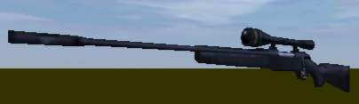
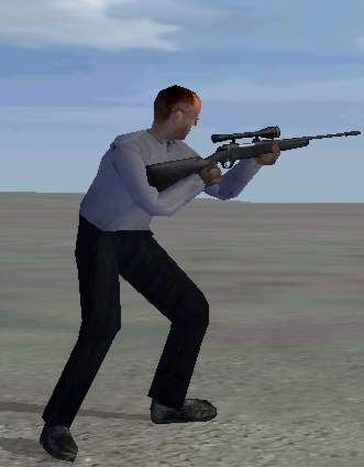
También puedes fusionar modelos que otros users han creado, por ejemplo otros rifles de francotirador descargados de la web. Solo usa PBOTool para descomprimirlos y echarles un vistazo al archivo p3d. Cuando hayas terminado de escalar y mover el arma a una posición, recuerda moverlo también en el LOD "0.000" y los vértices en las memorias LOD. Me temo que eso también es prueba y error. así es como mi modelo a quedado, bastante lindo no creen?
Una cosa, te habrás dado cuenta que solo creamos un modelo LOD, "0.000" en nuestro modelo. Normalmente tenemos al menos 3 diferentes modelos, uno mas detallado que el otro. Esto es para compensar las diferentes configuraciones de hardware y de como se ve el modelo a la distintas distancias. No tiene sentido cuando nuestro arma no tiene grandes detalles, a excepción del área del gatillo. Esto es muy importante de saber, sobre todo si vas a lanzar algún addon . Observa los demás addons y ve como están echos porque este es un simple tutorial en el cual no voy a tocar esos temas. No es tan complicado como debes creer para que no lo puedas aprender por ti mismo.
Pero ahora es tiempo de sentirse orgulloso porque acabas de crear tu primer arma en OPF! como es usual, puedes descargar el modelo terminado aqui.
Érase una vez una era oscura en la que los jugadores eran conducidos como ganado por rígidos caminos de juego. Bohemia Interactive fue la revolucionaria desarrolladora que los liberó.
Hello, and welcome back. Its time to make our first weapon in OFP. Yes, thats right. A step by step tutorial that covers the most of it; from modelling the gun itself to getting it ingame.
So, what skills do you need then. Lets see:
OFP (daahhh), O2 and Bulldozer Basic understanding of the O2 interface Having fully understud stuff from lesson1 (like creating LODs, selections etc) Also, if you made it through lesson 2, this should be an easy lesson. PBOTool and TexView
Ok, thats the most important things. Lets have a look at the model we are making:
The weapon
The gun we are going to make is nick-named "Stalker" and its a sniper rifle from Browning. Here, have a look:
Cool, isnt it? Well, it aint going to appeal to everyone, but its the gun we`re going to make. Why this one, you say? Well, first of all we got a great side-shot of the gun on their page, its mostly black (makes texturing-screwups easier to hide:) ) and most of all, it looks pretty cool!
So, here is what you need to do to get started:
+ Go to where Bulldozer is installed and make a folder named "stalker". + Download the texture files aqui and extract them to the folder.
When you`re ready to start, go to next page.
Placing vertrices
First we must create the actual gun model. Do this:
+ Fire up o2 and Bulldozer and save the new file as stalker.p3d in the stalker folder you made earlier. + Activate front view, press "A", click RMB (right mouse button) and select "load Texture". Find your Stalker folder and load the "blueprint.paa" file.
Load the texture we are going to use as reference.
+ The draw a box about, say 80% of the grid background. Then hit RMB and select "Correct Aspect" to ensure that the image dimensions are of the right scale. Also select "Horizontal Mirror" from the same menu so that the gun is pointing left. + Hit F4 to leave texture mode. The front view should look like this:
Now me must model the side shape of the gun. We do that by outlining the gun profile with vertrices. That means we use "insert" at various points around the model. Later we will create faces on these vertrices. Lets start with the back, shall we:
Zoom in on the rear gun part and start placing vertices using your cursor and the "insert" key. Start somewhere and work your way around the shape. Excatly where to place each vertex is not something you can learn just like that, it comes with modelling experience. Trial and error, that is. Here is how it could look like:
Note that there are few vertrices at the strait points and more vertrices where there are more round and soft shapes. Remember that we are dealing with polygons and therefore there are only straight lines between points. So we need to have many vertrices where the model is supposed to have a round shape.
Now lets have a look at the middle section (leave out the trigger area and the scope right now). Here is my suggestion:
Doesnt look too back, does it? The main shape is there, at least, Note that we are not going any more left right now, the front section (muzzle etc) will be made of a small cylinder structure later. The same goes for the scope; later.
Now for the hard trigger area. This is the roundest shape on side view and therefore need many vertrices to look good. Remember that the area between vertrices will be filled with faces, so we need an inner and an outer vertrice ring, like this:
Ok, so it aint perfert. Its sometimes hard to imagine how the vertrices will look once we have made faces, but dont worry. its easy to move them later. And we havent made the actual trigger yet, we`ll do that later.
What it should look like so far.
When you`re happy with your vertrices (If you aint, move them, add some or delete some to get the right shape), move on to the next step. And dont worry of some are a bit outside the background texture, "blueprint.paa" is only for reference, we use another one for the actual texturing.
Making faces
Now its about time to make the vertrices do their job. Lets start with the rear gun section. Making faces is easy, you select 3 or 4 vertrices and hit F6 to make a face. If you have read some basic o2 tutorials, you`ll know that every face has a "face normal" or a "direction". That means that a face is normaly only viewable from one side, the direction of the face normals (little blue lines poking out from each vertex). I assume you already know a little about this (if not, find a o2 interface tutorial or any 3d tutorial that deals with polygon modelling).
You should also heard that o2 supports faces created with 4 vertrices and not just 3 as in big-shot programs like 3dsmax. That way we can use less faces than normaly and still use 3-vertex faces when needed. We will select 4 or 3 vertrices and create faces on them using F6. Be careful to not overlap faces, that can make your model flicky and look bad ingame.
I`ll show you how to make your first face:
+ Zoom in on the rear gun section. We`ll start with a 4-vertex face. + Select the 4 vertrices as indicated on picture below:
+ Hit F6 and a face should be created.
Now we must make sure that the face is "facing" the right way. When I did this, my face direction was going from me in front view, not towards me as I wanted. So I had to reverse the face direction to make it the right way. Remember the trick I talked about in lesson 1, to see if the face is facing you? Go With the face selected, go to menu "View->Fill solid faces". Now, if the face is filled red, you know that it is facing towards you, but it if seem do disapear (it will go black and be hard to spot due to our black texture), it is facing the wrong way. To reverse the face direction, hit "W" key. Remember to make all faces face the same way during the rest of the page.
Now we have our first face. Note that we need to use a 3-vertex face just below our first one, since there are only 3 vertexes in that area. Select them using F4 (vertex select mode) and hit f6 again. Now o2 is pretty smart and it should face in the same direction as the last one, but check it out with the "Fill Solid faces trick" anyway.
Now , work your way around the rear part and create faces between the vertrices. Use 4-vertex faces where you can and 3-vertrex-faces where you have to. Make sure all is facing the right way and that noone overlaps eachother. You can delete a face without deleting the vertrices. Just select the face (F4 and all vertrices in the face) and delete it by hiting "D"-key.
Here is how it could look like when done:
Another great way to ensure all faces are in the desired direction is using the 3d view with "Face Culling" turned on (View->Face Culling or "F" key). When face culling is on only the faces that are pointing in the camera direction are drawn.
3d view with selected faces with face culling on. Since all faces are shown, they are facing the right way.
Let me show you why this feature is so great for searching out wrong-pointing faced. I will now select one of the faces and reverse it. Se what happened in the 3d view:
3d view with selected faces with face culling on. There is now a hole it our structure, which means one of the faces are the wrong way.
3d view with selected faces with face culling on. If we now move the camera and have a look at the back, we find our AWOL face again. As you can see, this is a much better and faster way to find bad faces compared to the "Fill Solid face"-trick I told you about earlier.
Now if you have understod the above, applying faces to the rest of the model should be easy. Just be careful, take it slow to make sure all faces are the right way and that noone overlaps eachother. Here is some pics of how it should look like:
Lets move on, shall we
Applying depth
So, our basic model is shaped up. Hey, it even looks like a gun, right now. But that only in front view (and finnaly, if you`ve been wondering why we have been using front view for our side shape, its because thats the way it is done with weapons. Dunno why. If we dont do this, the gun will be pointing in the wrong direction when someone tries to use it ingame). Right now its just completely flat. Lets do something about it:
+ Select the whole structure using Ctrl+A (or F2 on any vertex). + Activate left view without loosing the selection (Alt + LMB).
+ Now hit Ctrl+C to copy the structure. Then hit Ctrl+V to paste the new copy. It will be at the same spot as the original. + Lock the x-axis and move the copy a bit to the right using RMB.
+ Note that the copy`s faces are the same way as the original, to the left that it. But we now want them to point the other way, so with the copy selected hit W to reverse its faces. + Now it should look like this:
Front and 3d view with both structures selected. Note that here is faceculling turned OFF just to show up everything in a single picture.
Now we must patch the two sides togehter. That means selecting 4 and 4 vertrices and making faces. The easiest way to do so if using the 3d view. The hardest part in this is placing the camera right and selecting the right vertrices. I`ll help you with the first one:
+ Position the camera as in the picture below and select the highllighted vertrices.
3d view with face culling turned off.
+ Hit F6 to create the face. Then make sure that the blue lines are pointing out of the structure like in pic below. Use W tor reverse the face normals if not.
3d view with face culling turned off.
Do the same thing for the whole model! Yes, its hard and boring work, but its really good modelling practice. Make sure to select the right vertrices, its so easy to select the wrong ones if you are in a bad camera position. Use the other views combined with the 3d view as a guide. Afterwards use Bulldozer and the face culling trick in 3d view to look for leaks (faces pointing inwards of missing).
In the end, it should look like this:
3d view with face culling turned off.
Bulldozer view.
And, yes, one more thing. After you`re done, select the whole thing using Ctrl+A. Then, in left view, lock the x-axis and move the whole shape to the left. Try to place it so that the middle red line on the grid is in the center, like in picture below.
Phew, that was a lot of work, dont you think? Well, im glad to tell you that the hardest bits are over. If you made it so far, you should be fine in the next ones too.
Muzzle and Scope
Our gun is now really 3d, but its missing something, mainly the front section. We will make this one now out of a standard cylinder. Lets go:
+ Activate left view and hit F8 to create a cylinder shape. Use 8 in the "Segments Radius" and 3 in "Segments Z" .Hit ok.
+ Now in 3d view you`ll see the cylinder. Its pointing in the right direction but needs some scaling down.
+ Head for front view, and use RMB to move the cylinder to this position:
+ Lock the x-axis using x-key. Select each colum of vertrices using F4, and move them so that the result looks like pic below.
+ Now, select the two rightmost colums of vertrices, be careful not so select vertrices from the main gun structure. Choose Points->Transform3d->Scale from the menu. Leave the x-axis as 1 and try to find a decent value for the y and Z box (whatever the value, z & y must be the same value, or the cylinder will look squeezed). I cant give you an exact value, since your model might not be of the same scale as mine. But for me something around 0.1 for y and z worked fine.
+ Do the same thing with the last two colums of vertrices, but keep their y & z scale valuse a bit higher, since the muzzle is bigger in the front. For me, z and y values of .12 worked fine.
In the end, it should look like this:
Now we must create the scope and we use the same proccess as above. We create a cylinder with several divisions and resize each and everyone of them. We also need two boxes for the scope supports beneath it.
+ Activate left view, hit F8 and type enter the values below:
+ Go to front view and move the cylinder structure like this:
+ Then, like we did with the muzzle, lock the x-axis, select and move each colum so it eventually looks like below.
+ Still same thing as before, use 3d scale to get the right look and feel of the scope. Your values are not the same as mine, so experiment a little with the y and z value. Dont touch the x-value though.
The scope should end up like this:
Then we need the two blocks right below the scope to hold it in place. This should be easy for you to make now and you could make them by outlining the shape with vertrices, making faces, adding depth and fill in the gaps with new faces again. Just like we did with the main weapon profile in the start. Here are the ones I made:
The two structures for the scope. (Note: Moved them away from the weapon just to show them better on picture)
Anything more then? Yes, the trigger itself. It dowesnt show up on our picture, so we`ll just do some free-hand modelling. After all, this is just a tutorial and the model we are making are of pretty low-polygon quality. Here is how the one I made look like:
The trigger structure. (Note: Moved away from the weapon just to show it better on picture)
You`ve done it. The model is finished!
Now lets do some texturing, shall we?
Texturing
Now we must put some cool textures over our basic gray color. All textures are in the zipfile you downloaded at the start and should now rest in your stalker-folder. Lets go:
+ In front view,select all (Ctrl+A) so that everything is red. Hit A, RMB and choose load texture. Load the one called "stalker_tex.paa". Also, RMB and choose "Horizontal Flip" to make it face the right way. + Now, comes the hard part of scaling the texture so that it fits our model pretty accurate. Use Ctrl+Shift+Up/Down/Left/Right keys to scale it. Remember to RMB and choose "Correct Aspect" from time to time so that the texture doesnt get deformed. I know its hard, and it would have been easier if we had cut the texture in pieces, but try anyway. And remember this is a tutorial so there is no need to get it absolute right. I eventually was satisfied with this:
+ When you`re happy, with everything selected hit "B"-key and the texture should be applied to your gun model. Check it out in Bulldozer. Not bad, eh?:
So, its not going to win a beautycontest, but it doenst look too bad for a tutorial model. At least not that bad, anyway. I think it looks pretty cool. One thing though, it could need a better front and rear for the scope, some glass-looking texture. There is one in your stalker-folder so lets apply it now:
+ In front view, RMB click and choose "unload texture" to remove the texture. We`re done with that one. Now, zoom in on the scope front, hit F4 and select the scope front colum like this:
+ Activate left view without loosing selection (Alt+RMB), hit A key, RMB and load the texture named "scope_glass.paa" + Draw the texture box around the scope face. Use Correct Aspect to ensure right image dimensions.
When you`re happy with your texture placement, hit B to apply it to the scope. Check it out in Bulldozer and try again if you messed it up. This is my result:
Now do the same thing to the other end of the scope. Just follow the same steps as above. Select the rear scope vertrice colum using F4 in the front view, go to left view and scale the glass texture so it fits the smaller scope end nicely. Then applying it with B and check out in Bulldozer.
Here is my result.
And that way texturing, my friend. Now the hard modelling is over, just some simple LOD stuff and the making of a basic config-file for weapons left. Go go go!
Memory LOD
As in all ofp addons, we need to sort things out in LODs. But for guns we only need one, the MemoryLOD. And it contains only 4 vertrices! Simple stuff, really. Lets begin:
+ Create a new LOD and change it to "Memory LOD" by RMB and choosing "propeties". + Go to front view and zoom in on the barrel like picture.
+ Place a vertex on the center of each end of the barrel. They must be on the same height (or the gun will not shoot strait), so make only one, lock x-axis and drag-copy the next one using RMB+Shift and move. The result should look like this:
+ Then, remember in many of the LODs in Lesson 2 we selected and named single vertrices and called them names using czech words?. Well, do that now and call the vertrices the names on the picture above. "Konec hlavne" means end of barrel and "usti hlavne" means start of barrel. If you dont know how to save selections, see lesson 2.
Now the gun can fire right. But we also need to indicate where the gun should spit out the empty cartridges. Just like the barrel, we need a start and stop position since the cartrides are "shot" out of the gun. Their placement isnt all that important, so I just give you a 4-view picture of how I positioned them. Save each of them as selections named as in picture. "Nabojnice" means cartridge-case in english.
Finally, we need the 5th and last named selection called "zbran", which simply means weapon. The selection consist of all four vertrices, so just hit Cltr+A in Memory LOD and name the selection "zbran".
Here is the selections you should have made in this part:
Thats all the LODs we need for a weapon addon. No kidding. Move on.
The muzzle flash
Well, ok so we werent all done with the modelling stuff. I guess I lied a bit there. But this is very simple.
If you dont already know, the flash that occurs when firing most guns in OFP is no fancy special lightingeffect or anything. Nope, its just a simple model with transparent smoke-textures on it that occur the split-second the weapon is fired. Disappointed? Dont be, because its easy to make and looks good enough anyway.
Have a look in your stalker-folder and check out the two textures flash_side.paa and flash_front.paa.
Lets get this over with quickly, then:
+ Go back to the "0.000" LOD. + Activate the top view and then find "create-plane" on the menu. Hit ok. Just after you hit OK on the dialog, hit F6. The blue lines (indicating face direction) should go away and the plane is now a double sided face. It is now viewable from both sides, check it out in Bulldozer and 3d view with Face culling on and then off. Cool, eh? + Now move the plane along the x-axis in top view (using lock x-axis), make it a bit more like a rectangle. Then, in front view, lock the y-axis and move it upwards. It should look like this in front and top views:
+ Now we apply the flash_side.paa to the plane. Since this is a double sided plane, teh texture will be viewable from both sides. Activate top view, zoom in on the plane and hit "A" key. RMB click and choose Load texture. Load flash_side.paa and drag teh texture around the plane. Make sure that BOTH sides on the plane are select, not just the one. Do that by making sure that both sides are grey in Bulldozer. If one is red like the rest of the gun, use F2 and select one of the plane vertrices. Then apply the texture using "B" key. + Check it out in Bulldozer. It should look like this:
+ Now that we have one horizontal muzzleflash plane, we could need a vertical one. This time we simply copy the one we made and rotate it. + Select the flash plane, Ctrl+C to copy and Ctrl+V to paste. Then on the menu find Transform3d->Rotate.. and rotate the new copy 90* on its X-axis (if you have the front-view active, that is). The result:
We need one other muzzle flash, a circle for the flash_front.paa so that the flash is visible when looking strait at the firing gun (aka getting shot at).
+ Activate the side view and find create->circle on the menu. Make the "Segments Radius" from 10 to 6 and hit ok. Move and resize the circle so that it looks like this in 3d view:
3d view with face culling OFF
+ But we need doublesided faces, so with the cricle selected, press "D" do delete all faces on the circle so that only the vertrices are left, like this:
3d view with face culling OFF
+ Now we must make two doublesided faces by using F6 twice (!) on each face. In Select the 4 upper vertrices and hit F6 twice.
+ Then select the bottom 4 vertrices and hit F6 twice to make the lower face.
+ If you`ve done everything right, you should see a roundish-looking shape at the barrel end with both sides visible in Bulldozer.
Now we need to texture it. Thats easy, aint it? You`ve done it many times before. Just select the circle using F2, hit "A", load the flash_front.paa, draw around circle in side view then apply it using B-key. Routine, isnt it?. Soon second-nature, I hope. Well, anyway, this is the final result:
Ok, almost done with our model now..hang in there. We need two simple named selections in our primary LOD, "0.000". OFP needs to know what parts are the gun model and what parts are the muzzle flash. So select all the muzzle flash parts (3 structures, two planes and a circle), and name them "zasleh" ("flash") in the named selection window. Then you need to select all the other parts; muzzle, main gun body, two scope holders and scope, trigger, hmm..anything else?..no. Name that selection "zbran" (weapon).
And if everything is done correctly, you are now finnished with the model! Great job. Look trought the previous steps and make sure everything is right. And check that the texture paths are right (we learned how in lesson 1). Ok, done?. Configfile next, then.
The weapon config-file
Only one obstangle away from testing our model in-game. Now that has to be good thing, doenst it?. Well the bad thing is that our configfile is on the wrong side of "very confusing" for a any beginner. So, as Ive done before, I will lay out the configfile and explain only some key attributes and leave the class-inheritance stuff for you do learn from an other tutorial. In fact, you could just move on to the next step if you want, but I advice you to read this and at try to get an overview of what is going on in the configfile.
Snippet from the most important part of the config-file. There are more stuff in the configfile, but only the above is the interresting parts right now.
If you have some ObjectOrientet programming experience, you`ll see that Ive inherited (aka "stolen") most of the M21 sniper rifle and changed some key attriutes. The ammo is regular sniper ammo and both the gun and ammo have the same name (so if you are to add the gun and ammo to a person in the editor you would write this AddWeapon "Stalker"; this AddMagazine "Stalker";. The displayname is "Stalker Sniper Rifle" and Ive also prepared a small photo of the gun for the ingame journal on the map screen called "photo.pac".
Then Ive also made a civilian equipped with the gun. He is called "Stalker Hunter" and carries the rifle with 4 magazines. There are 20 bullets in each magazine, just as the M21.
Ok, enough config-file now. Lets just leave it alone and test our model ingame instead. Roll on.
Finishing up
Ok, lets do this. Its time to test it ingame! Run PBOTool, select the stalker-folder and save it as stalker.pbo in the OFP addons folder. Then start up OFP. Go to the editor and find the civilian called "Stalker Hunter" on the Civilian->Man list. Then come back to the lesson after testing.
You`re back, huh? What? Something is wrong, you say? The gun is bigger than an airplane? Like this, for example:
Now THIS would be fun in multiplayer. But its more like "Big Bertha" than "Stalker"....
Well, thats right. Its not scaled right yet. Hey, at least it is pointing in the right direction! And it works, doesnt it? With sound, cartridge shootout, muzzle flash and proper scope? Not bad, eh?
You need to use the 3d scale tool in o2 to make it the right size (remember when scaling to tick on the checkbox "Apply to all LODs" so that the vertices in Memory LOD follows the rest of the model). Normaly this is just trial and error. Scale it down a bit, compile and test it. It it still too big, do the same thing again. Im not sure how big the thing is in real life, maybe the web site can give you a clue. Just remember that each grid square is 1 meter.
One thing you can do to help you, is to "merge" a p3d file of an other sniperrifle, like the M21 or the Dragunov. That will make it easier to scale your own model. Also, it will give you a hint on how the model should be placed to rest nicely in the hands of a soldier. Note that you cant load up the M21 model from your OFP copy since the developers have crypted their files. But they didnt lock up the model files from the first single player demo of OFP. So if you want a p3d model of, say, the M21 sniper rifle, go to my links-page for clues on where p3d`s from the demo can be downloaded.
You can also merge usermade models, other sniper rifles downloaded from the net. Just use PBOTool to unpack them and have a look at their p3d file. When you`re done scaling and moving the gun into position, remember to move both the gun in "0.000" LOD AND the 4 vertrices in Memory LOD). Thats trial and error too, im afraid (if you havent downloaded any demo or unofficial addon p3ds, that is).
Here is how my model looked like in the end. Pretty cool, I think.
One thing, though. You have noticed that we only have one model LOD, "0.000" in our model. Normaly we have at least 3 different models, one more detailed than the other. This is to compensate for the different hardwaresettings and the distances the model is viewed from. No point in having the machine draw small details, like the heavy-polygon trigger area when the gun is view from a distance far away. This is very important to know if you are to release any addons. Look at other addons and see how its done, because since this is just a simple tutorial Im not going to cover this here. Its not that hard and you should be able to figure this out for yourself.
But now its time for you to feel proud because you just made your first weapon in OFP! As usual, you can download the final model aqui. And I welcome any feedback on my lesson on hotmail.com (or via MSN directly, I`m online almost every day).
That concludes lesson 3. Happy sniping.
_________________
Érase una vez una era oscura en la que los jugadores eran conducidos como ganado por rígidos caminos de juego. Bohemia Interactive fue la revolucionaria desarrolladora que los liberó.
No puede abrir nuevos temas en este Foro No puede responder a temas en este Foro No puede editar sus mensajes en este Foro No puede borrar sus mensajes en este Foro